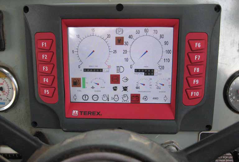
Today’s Rated Capacity Indicators (RCI’s) are much more sophisticated than in the past and have real time data logging of all the crane operating parameters and may also include displaying engine and transmission parameter information and machine service intervals.
Mobile cranes having state of-theart RCI’s which are all based on Load Moment require a procedure to ensure the accuracy of their measurement and readouts which should be undertaken by the operator before each shift, once a week by a designated competent person and thereafter every 6 months by a Lifting Machine Inspector having the knowledge and experience on such devices.
Let us look at why we need Load Moment based Indicators on today’s modern mobile cranes.
In the past crane operators often relied on the “feel” of the crane to determine the limit of the machine’s capacity. The operator would “sense” the crane moving which was generally when the load on the outriggers lightened. In other words if he was lifting a load over the rear of the crane the front outriggers would become loose and once this occurred he and the riggers knew the crane had reached its stability limits for that specific configuration.
He was in effect using the stability of the machine to sense Load Moment. In the past cranes were heavily constructed where the structural capacity exceeded the stability limits of the crane but over the past 15 to 20 years crane manufactures are now utilising higher yield steels and more recently carbon fibres to create a stronger and lighter crane which has had two dramatic effects.
The structurally limited portion of the capacity chart has increased, and in some instances the entire chart has been incorporated to be based on structural strength only. A failure of the crane due to an overload can be sudden and without warning.
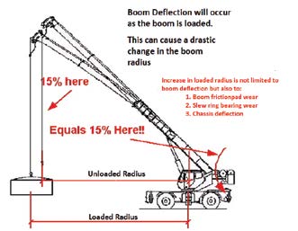
Due to utilising lighter boom and chassis with more elastic material boom deflection has increased dramatically. This is extremely important because as the boom deflects under load the actual load moment increases as does the load radius. This now increases the Load Moment proportionally.
The modern RCI’s take boom deflection into account with or without load as well as the increase in load moment and any dynamic effects on the crane structure.
Note: Mechanical influences can and do effect load radius for example wear to the boom slid pads, slew bearing wear and elasticity of the crane’s chassis.
How to verify the rated capacity indicator parameters
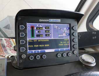
There is a simple way that will allow you to confirm the accuracy of the RCI. This is by comparing known values on the crane’s capacity chart against the readings on your RCI display.
The first step is to place the hydraulic crane on firm level ground and extend the outriggers to the fully extended position. Level the crane by using an inclinometer – Do not rely on the cranes level indicator! (try to keep the cranes super structure in the most stable and safe position).
Boom angle and Length verification. Position the machine with the boom fully retracted and at the lowest position (min. angle/length), check the display readouts which should correspond with the crane’s duty chart. Now, raise the boom roughly 5 degrees from maximum boom angle (using an inclinometer) at the same time extend the boom fully to the end of the cylinders stroke and again the RCI display readings should correspond with the duty charts information for max length/angle. Should any discrepancies be found it should be reported immediately to the relevant person responsible for the crane and must be rectified before proceeding with any further tests. Accuracy should be typically less than 2%.
Radius/Load verification – for this you will need a 30m tape and known test weights. Position the cranes boom at an angle of approx. 60 degrees and a boom length roughly two thirds of the maximum length within the crane’s capacity. Place the main hoist hook block over the centre of your test weight, now measure the radius using a 30m tape from centre of rotation to the centre of the hook block and record actual and RCI display readings. Now lift the load just off the ground and again record the readings against the RCI’s readings. Loaded radius should increase. Accuracy should be typically for Radius 1% and Load 2%.
Note: the actual load must include the weight of the Load + Hook Block/ Blocks + all Rigging Gear.
To confirming the crane motion cutout system is working, simply raise the main hook block and activate the hoist limit switch.
If there are discrepancies in any of the actual readings and RCI displayed readings or motion cut-out not activating, it is strongly recommended that the crane is removed from service in the interest of safety until the system is repaired and recertified.
The above is a verification procedure and not a system calibration examination/test which must be performed by a competent person who has the knowledge and experience on rated capacity indicators and is in a position to certify such a system.
Cranemec Group are distributors for COBO-3B6 RCI’s as well support GREER and PAT KRUGER with service and parts. If there are any questions on the verification procedures or you would like to know more about RCI’s, please do not hesitate to contact Cranemec Group S.A.